
These tests are not "real-world", since they are not a staged speed-trap situation. Instead, these tests take a different approach: they are designed to determine the raw capabilities of the radar detectors, which can be applied to the real world. Why "semi-scientific"? Because we don't have access to tens of thousands of dollars in lab equipment, and also lack the controls of an isolated lab environment. But we do our very best to remove as many variables as possible, leaving only the performance differences between the radar detectors.   A big thanks goes out to: BuyRadarDetectors.com for sponsoring us by loaning us several brand new retail radar detectors for the test! The main focus of the off-axis test was to compare the off-axis performance of the top dash mount detector from each company. Several different detector models may share the same antenna, so testing these units may be a good indicator of off-axis performance for other units using the same antenna. We tested the detectors by exposing each one to a specific set of controlled conditions.
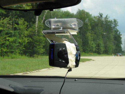
The radar was aimed straight down the test course. The test vehicle proceeded down the test course and stopped at the first alert from the detector under test. The distance back to the radar vehicle was measured by using an LTI Ultralyte in survey mode. We did test runs with each radar detector rotated at 0, 10, 20, 30, and 40 degrees, to each side. A special test fixture was constructed which allowed us to easily pivot the detectors to specific angles while they remained mounted level. We didn't make it a point to take photos of the fixture for this test (modified for 10-degree increments), but below you'll find some photos of the fixture from a past test. 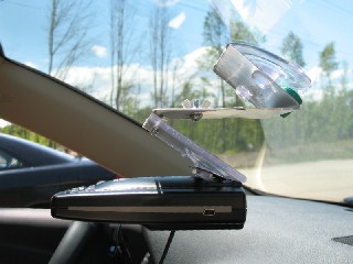
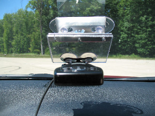
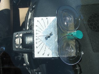
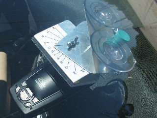
Please remember: degrees are approximate. Obviously the test fixture wasn't made to exact tolerances. For these tests, we used radar absorbent foam. 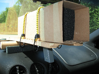
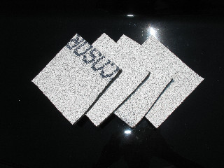
Eccosorb is specially-designed foam which absorbs radar. In this test, the Guys of LIDAR used layers of Eccosorb in front of the radar antennas to reduce the radar signal, or make it weaker. Why? Because a detector's job is to sniff out weak signals. The further away you are from the radar, the weaker the signal becomes. Today's high-end radar detectors can detect radar miles and miles away in the right situations. Because of this, radar detector tests commonly use hills, terrain, or other means to reduce the radar signal for test purposes. But every test situation is different, and these methods can sometimes yield sporadic results. Enter Eccosorb. The Eccosorb allowed us to reduce the radar signal in a highly-controlled manner, and allowed us to test on a straight course under highly controlled conditions. This method of testing also reduced or eliminated some of the unpredictability that occurs with other methods, and yielded highly-repeatable results. In addition to the Eccosorb in front of the radar, the sides and rear were also surrounded with Eccosorb just for good measure to help prevent any stray radar reflections. Please remember: what these test results provide is an indication of "relative sensitivity", or how the detectors might compare against themselves or each other. Just like any other radar detector test (foam or not), the absolute distances in the results cannot be applied to any situation other than the specific test conditions. In this test, just like any other detector test, it's the ratios that matter. In the past, we've had some people ask: "Why did you keep the radar stationary, and turn the detectors? Why didn't you turn the radar gun? This doesn't make any sense, because that isn't what would happen in the real world". To explain a bit, these tests are focused on determining the raw capabilities of the radar detectors. Each radar detector antenna has a receive pattern, but likewise each police radar unit has its own antenna pattern. If we were to mount the radar detectors in a fixed position, and instead rotate the radar gun, we would basically be exposing the front "lobe" of the detector to the radar gun's changing antenna pattern as it rotates. This wouldn't tell us anything about the off-axis receive capabilities of the radar detector. However, it would be useful if we wanted to know the antenna pattern of the radar gun. Might be interesting information, especially if we were comparing different radar gun models. But the goal of this test was to compare the performance of the radar detectors, not to compare the antenna patterns of radar guns. If you still don't understand, or don't like it, then click the back button, and go to the real-world page.... we have something for everyone.         Some people have been wondering lately how mounting radar detectors on their side effects off-axis performance. So, we decided to find out how the detectors would perform off-axis... on the other axis! This may also be a good indicator of over-hill performance, and will also show how much performance you can lose if your detector isn't mounted level. For these tests, we used some special mounts which are sold overseas to increase radar detector performance against linear polarized photo radar (more on that later). 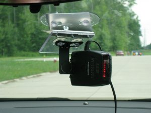        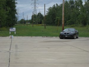 We don't have as much photo radar in the states as they do in some countries overseas, and people that don't face it as a threat should consider themselves lucky: it can be difficult to detect, because 1) many units are low powered, and 2) many units are "horizontally polarized". Most regular police radar is "circular polarized" with the exception of the Stalker ATR, and a couple of new K-Band units from Kustom signals. Radar detectors are vertically polarized when mounted normally, in the horizontal position (Got that?). Detectors are designed this way because horizontally polarized radar waves are attenuated (sometimes a lot) by sloping vehicle windshields, while vertically polarized radar waves are much less affected. So, more range can be obtained by trying to detect the vertical polarized waves as long as the radar source isn't horizontally polarized. When the polarization doesn't match the radar source it can have a devastating effect on range. How much? That is what we set out to discover. People who face horizontally polarized photo radar as a threat learned a long time ago to mount their detectors "on their side", because when a detector is mounted on its side (in the vertical position) it is horizontally polarized, matching the polarization of the photo radar. Special mounts are manufactured specifically for this purpose, and these are what we used for the test. 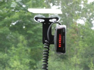 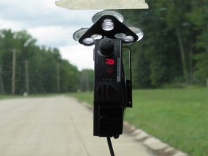 It would be nice if we had an actual photo radar unit to test against, but other than finding one in the "wild" to test against, our chances of getting a hold of one for testing are slim. So, we decided to simulate it. The Stalker ATR is the only known Ka unit in the US that is linear polarized, but unlike photo radar it has plenty of transmit power and it is vertically polarized. So, we used Eccosorb to attenuate the radar, and mounted the gun on its side so that the detectors would face a low-powered, horizontally-polarized, Ka threat... not quite on 34.3 GHz like overseas photo radar, but close on 34.7 GHz. We also angled the radar at about 22.5 degrees across the lane of travel. Each detector got two runs mounted normally (in the horizontal position), and two runs with the special mount in the vertical position.   |
HOME | Tests & Reviews | FAQ | Technical Info | Articles | Videos | Links
About GOL | Contact Us | Terms of Use | Site Map