

If you're scared of the foam, or can't handle the truth, then
EXIT NOW!
You've been warned!
 An "off-axis" radar detector test hasn't been done before, at least not in recent history. So, the Guys of LIDAR spent two days testing the most sensitive radar detectors to see how they would respond when encountering radar at different angles. 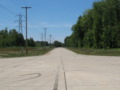 We used the test course that we normally use for laser jammer testing: a 2000+ feet of straight stretch at the end of a dead-end road. The capability of a radar detector to detect off-axis radar relates directly to the design of it's horn antenna. These types of antennas are directional by nature, but just how directional are the individual designs used in today's top radar detectors? Our test was designed to help answer that question. Since many different models of detectors use the same "platform" along with the same horn antenna, we selected one example of each of the top four most sensitive platforms ever produced. Three of these platforms are in current production, while one platform is from the recent past but is no longer produced (included as a reference). Currently, no other detectors use this platform, although the STI-R will be using it when it becomes available. Escort 8500 X50 - "S7" Platform This platform is no longer produced, and was superseded by the "M4" platform. Escort 9500i - "M4" Platform Valentine One v3.858 Valentine research does not have multiple models, so nothing else uses this platform. 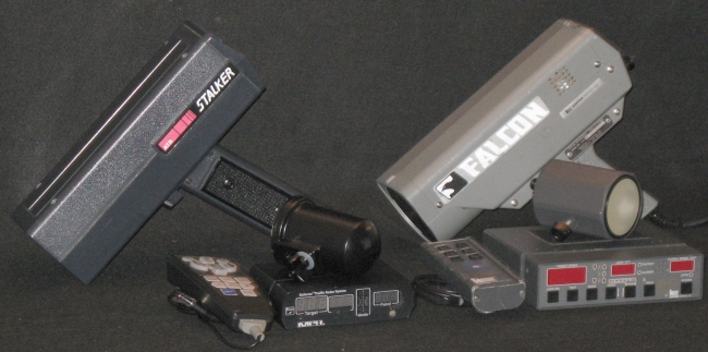 We used the following radar units:
 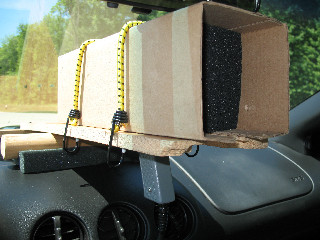
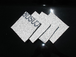
Sorry to disappoint, but the foam doesn't look all that evil. Eccosorb is specially-designed foam which absorbs radar. In this test, the Guys of LIDAR used layers of Eccosorb in front of the radar units to reduce the radar signal, or make it weaker. Why? Because a detector's job is to sniff out weak signals. The further away you are from the radar, the weaker the signal becomes. Today's high-end radar detectors can detect radar miles and miles away in the right situations. Because of this, radar detector tests commonly use hills, terrain, or other means to reduce the radar signal for test purposes. But every test situation is different, and these methods can sometimes yield sporadic results. And for this test, we needed conditions where the angle of the radar vs the detector could be precisely controlled. Enter Eccosorb. The Eccosorb allowed us to reduce the radar signal in a highly-controlled manner, and allowed us to test on a straight course where the angles could be precisely controlled. This method of testing also reduced or eliminated some of the unpredictability that occurs with other methods, and yielded highly-repeatable results. In addition to the Eccosorb in front of the radar, the sides and rear were also surrounded with Eccosorb just for good measure to help prevent any stray radar reflections. Please remember: what these test results provide is an indication of "relative sensitivity", or how the detectors might compare against themselves or each other. Just like any other radar detector test (foam or not), the absolute distances in the results cannot be applied to any situation other than the specific test conditions. In this test, just like any other, it's the ratios that matter. We tested the detectors by exposing each one to a specific set of controlled conditions.
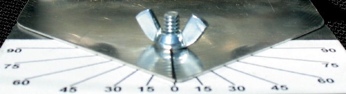
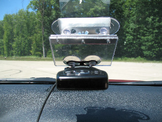
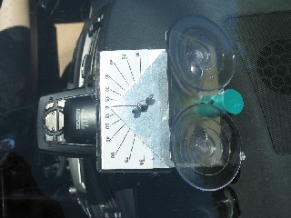
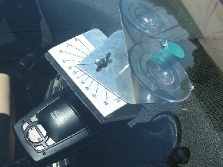
The radar was aimed straight down the test course. The test vehicle proceeded down the test course and stopped at the first alert from the detector under test. The distance back to the radar vehicle was measured by using an LTI Ultralyte in survey mode. We did test runs with each radar detector rotated at 0, 15, 30, and 45 degrees. A special test fixture was constructed which allowed us to easily pivot the detectors to specific angles while they remained mounted level. 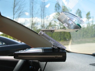
NOTES:
Ka Band - 33.8 GHz Averages 
Ka Band - 34.7 GHz Averages 
Ka Band - 35.5 GHz Averages 
K Band - Averages 

In addition to the detailed testing above, we also did some experimenting. We used less Eccosorb so that we would have a stronger radar signal, and we positioned the test vehicle at 1000 feet from the radar source. We set the detectors at 90 degrees, and then slowly rotated them towards 0 degrees until we got an alert. We did this for both the left and right sides. Unfortunately, these results aren't very conclusive, because this scenario puts all detectors against each other at 1000 feet, regardless of sensitivity. This would be more conclusive if all of the detectors were equal in sensitivity, but of course that is not the case. We decided to publish the results anyway, just for reference. 
|